 gaetano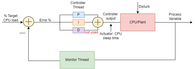
Motivation
Accurate CPU load generation is essential for systems and performance engineers. Whether testing thermal management, power budgeting, or application behavior under load, precise control over CPU utilization is critical. Traditional load generators either max out the CPU or provide coarse-grained control. This project implements a PID-controlled load generator that maintains exact target CPU utilization through feedback control.
Use Cases
- Performance Testing — Simulate realistic workloads on servers and applications
- Resource Allocation — Test kernel scheduling and resource management algorithms
- Benchmarking — Establish consistent baseline performance metrics
- Education — Teach control systems theory in practical contexts
- Thermal and Power Analysis — Characterize thermal profiles and power consumption at specific load levels
PID Regulator for Controlling CPU Load
The Monitor Thread samples CPU load at regular intervals, filters measurements with a first-order filter, and logs various parameters over time. The value measured by the Monitor Thread is calculated using the psutil method cpu_percent(interval) which calculates CPU usage during the specified interval. The call cpu_percent blocks the thread for the interval duration, ensuring the loop naturally waits for the specified sampling time before proceeding to the next iteration.
Controller Thread
The Controller Thread compares the CPU Load measured by the Monitor Thread and the Target CPU Load desired (also known as the set point). Based on the difference between them (the tracking error), the PID regulator computes a control signal and sends it to the actuation device. When the error is fed to the PID regulator, it computes the P (proportional), I (integral), and D (derivative) contribution of the error signal with respect to time. In this project, the derivative contribution is not used. The proportional and integral components are weighted by coefficients and then summed. The output of this operation is the actuator signal, which in this case is the sleep time used in the actuator function that generates CPU load:
    def generate_load(self, sleep_time):
        interval = time.time() + self.period - sleep_time
        # generates some getCpuLoad for interval seconds
        while time.time() < interval:
            pr = 213123  # generates some load
            _ = pr * pr
            pr = pr + 1
        time.sleep(sleep_time)
In a nutshell, if the error is positive we need to increase the CPU Load by reducing the sleep_time of the actuator function. On the other hand, if the error is negative we need to decrease the CPU Load by increasing the sleep_time.
Tuning of the proportional kp and integral ki coefficients has been made through an extensive campaign of experiments. The PID regulator function is the following:
    def run(self):
        def cpu_model(cpu_period):
            sleep_time = self.period - cpu_period
            return sleep_time

        self.shutdown_flag.clear()
        while not self.shutdown_flag.is_set():
            # ControllerThread has to have the same sampling interval as
            # MonitorThread
            time.sleep(self.sampling_interval)

            # get all variables
            with self.target_lock, self.cpu_lock:
                CT = self.CT
                cpu = self.cpu

            self.err = CT - cpu * 0.01  # computes the proportional
            #  error
            ts = time.time()

            samp_int = ts - self.last_ts  # sample interval
            self.int_err = self.int_err + self.err * samp_int  # computes the
            #  integral error
            self.last_ts = ts
            self.cpuPeriod = self.kp * self.err + self.ki * self.int_err

            # anti wind up control
            if self.cpuPeriod < 0:
                self.cpuPeriod = 0
                self.int_err = self.int_err - self.err * samp_int
            if self.cpuPeriod > self.period:
                self.cpuPeriod = self.period
                self.int_err = self.int_err - self.err * samp_int

            self.set_sleep_time(cpu_model(self.cpuPeriod))
Anti-Windup Control
The anti-windup control ensures that the PID action does not generate a negative cpuPeriod or a cpuPeriod larger than the actuation period.
PID Regulator Insights
Here are some considerations on the PID regulator and why proportional action alone is insufficient. Increasing the proportional gain (kp) proportionally increases the control signal for a given error level. This means the controller will "push" harder for the same error, causing the closed-loop system to react more quickly but increasing the risk of overshoot. Another effect of increasing kp is that it tends to reduce, but not eliminate, the steady-state error.
Adding the integral term to the controller (ki) helps reduce steady-state error. The integral term accumulates error over time, increasing the control signal and driving the error down. However, a drawback of the integral term is that it can make the system more sluggish and oscillatory. When the error signal changes sign, it may take a while for the integrator to "unwind" — which is why anti-windup mechanisms are also needed.
Results
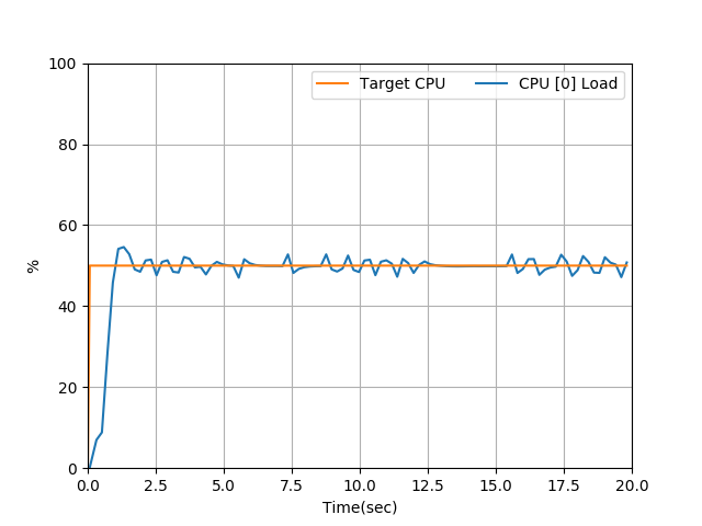
The tool can be tested easily by creating a code space on GitHub. Example: generate 55% load on core 0, 12% on core 3, until the program is interrupted via Ctrl-C:
./CPULoadGenerator.py -c 0 -c 3 -l 0.55 -l 0.12Project Links
- GitHub Repository: CPULoadGenerator
- Run in GitHub Codespaces (no local setup needed)
- Control Systems Academy: PID Tuning Guide